Tuesday, May 7, 2013

Final Project Progress - Roadway Design

    I continued working with Generative Components this week, trying to enhance my adaptive roadway.  It took a while but I think I finally got the hang of GC, at least the simple features and the syntax for the more difficult functions.  I was able to successfully incorporate conditional statements (if else statements) and for loops within my transactions in GC allowing me much more complexity with my model.  Learning the syntax and the process for creating these functions however, took a lot more time than I had hoped.
    But it was worth it.  These functions allowed me to alter the roadway pitch to create a crown in the roadway or super-elevation around a curve.  GC decides when to do this by itself based on the curvature of the centerline of the roadway.  Furthermore, it allowed me to program into GC when to create columns under the roadway if the roadway rose up farther than 2 feet from the ground line (2 feet was a random number I had chosen but it can be changed).  After seeing the effect of the columns I realise that I have to add some transverse beams at the columns but that is for another day.
    The hardest part at this point is coming up with the correct ratios in order to obtain the correct pitch of the roadway and the number of generated cross-sectional lines used to loft the roadway surface.  Also, the tolerance variable of when to super-elevate the road is a little tough to estimate (ratio) correctly.  I attempted to ensure that my model was a 3D object so it can be 3D printed but I am not sure how the STL file came out.  The first attempt at 3D printing will tell a lot.
   Check out some of these attached images from my model.  Just to note, the roadway width and number of lanes are still controlled through variables, even though I left them constant for comparison purposes in these pictures.


Tuesday, April 23, 2013

Roadway Attempt in GC

   I continued my exploration in Generative Components this past weekend.  I have found that while I like the overall layout and functionality of the program better than others that I have tried, it is taking me longer to learn the particulars about GC (such as syntax, where features are, how to accomplish certain things, etc).  With this additional time spent in the learning curve, I was only able to get as far in GC as I had done last week in Grasshopper.  I once again created a roadway, made as a solid, and based on certain input variables that control the dynamics of the object (such as number of lanes in each direction, lane width, roadway thickness, etc).  I did further research into the Boolean functionality (such as "if" statements) and found that they are much easier to implement than in Grasshopper.  However, I found that it was more difficult for me to control the physical appearance of the object (such as color and dashed lines) than it was in Grasshopper, and I haven't quite been able to implement the visual aspects as much as I would have liked.  I plan on sticking with GC from here on out based on our discussion of what was upcoming for the rest of the semester.  I feel like once I get the hang of GC I will be able to create some pretty interesting models.


Friday, April 19, 2013

Generative Components Exploration

   I was able to spend a good portion of time today working with the Bentley Generative Components program and going through the tutorials.  As was said in class, this software is so far ahead of anything that I have ever seen it is unbelievable.  It is my new favorite software and I have very little idea how to use it.  It combines written code with the digital modelling aspects of Microstation, best of both worlds.  Plus I like the interface that it gives you including the easy 3D control and visualization in the modelling window.  I haven't found the advantages of the simple graphical code view yet (the one similar to grasshopper) but I am sure that I just haven't come across its usefulness at this point.  I also like the feature that allows you to view the entire transaction code in the transaction dialogue box, yet I can't follow the code (c#) quite well enough yet (just a matter of time).  I can't even begin to imagine the capabilities of this program.  I was working through trying to import point locations into Microstation from an excel file on my own time and finding that I needed to do a lot of research, but it seems if I use GC it should be easy.  You even get an excel looking database interface when working in GC if you are using certain features.  Plus there are lots of tutorials on this topic as it seems that GC was made with this in mind.
   After going through the first 4 tutorials, I realize there is still a lot to learn and it will take a very long time to get used to it (probably years to master if that is even possible).  Because of this, I feel like my capabilities in this program are currently limited, but I plan to try to see if I can create something on my own this weekend, at least as a trial (outside of tutorial help).  I will however urge everyone in the class to block out a large portion of time if you want to go through the tutorials correctly and start to learn just the basics of the program; it really is that complex (but worth it in my opinion).
    As a couple of tips, it is hard to keep remembering to save your transactions but it is a very important step.  Also, remembering to hold ctrl down when selecting points (or objects) as input into functions is important.  It also helps to keep a running list of your point and variable names, GC does this for you but it is difficult to access and figure out which point is which when you are in the script editor (you can choose a point but I was finding that I would forget which one to choose, and I couldn't select it in the model window with script editor open).  Furthermore, explore Bentley's online help documents in their communities website.  There is a lot of good help there.  With that said, it is hard to find and navigate through their website.  I would have never guessed that a company that can create such amazing software had what seems to be some trouble creating an easily navigable website.  After searching for some time you will find that they have very helpful information on there website though, such as this link providing a good source of written information from Bentley about some of the basic features in GC:
   Take a look at some of the images from my first couple of attempts with the tutorials.  The images don't even come close to showing the capabilities of the program but are interesting none-the-less.


Sunday, April 14, 2013

Grasshopper Model Roadway

    As described in my previous post, over the last couple of days I was able to watch and replicate a number of grasshopper tutorials as I began to learn the program.  I starting this morning by replicating the tower mass tutorial from DesignReform.  It served as a reminder about the different commands and processes that I had learned in the program the previous week.  Then I felt inspired to see what kind of code I could create in grasshopper from scratch.
     My first attempt was to create a roadway that I could specify particular inputs for and have the entire object redefine itself.  All I wanted in the rhino model was the center-line curve of the roadway, all other aspects of the roadway should build themselves around the center-line   That way I could change the geometry of the road through the center-line curve in rhino and the roadway would stay intact (automatically update).  I also wanted to be able to control inputs such as number of lanes, width of lanes, thickness of roadway, color/material of roadway, color of parapets, etc, right within grasshopper.  I have plans to see if I can create a code to manipulate buildings next, and I was even contemplating the idea of creating a code that produced a gusset plate for a truss bridge based strictly off of the AASHTO and FHWA structural codes.  I would hope that the only thing the grasshopper code would need is input of member forces and angles framing into the gusset plate.  All other values and dimensions (such as gusset plate size, shape, thickness, number of bolts, bolt spacing, etc) would then be calculated within grasshopper and displayed in rhino.  Since it would all be derived from the structural codes, it would be an acceptable design for a gusset plate in real life.
     There were a couple of things that I found helpful throughout my week of learning this program.  First of all there are a lot of good explanations of the program components on the web, especially http://digitaltoolbox.info/grasshopper-basic/ and http://www.designreform.net/.  Also, I found myself using the offset function quite a lot.  This way I could create the geometry that I want right in grasshopper and have it update in rhino when other things changed.  Furthermore, I found that the option to "flatten" a stream of data can prove to be very useful when you can't figure out why something is not working.  At the conclusion of my first week with this program I think it is amazing and can't wait to further explore its capabilities and push its limitations.

TOWER MASSING TUTORIAL


ROADWAY DESIGN


Saturday, April 13, 2013

Learning Grasshopper

   After watching the grasshopper tutorials this week and getting a feel for the program interface, today I was successfully able to recreate 4 out of the 5 tutorials from the DesignReBuild website.  The 5th one I am planning to try tomorrow as a warm up before I create my own grasshopper file from scratch (not using a tutorial).  Thus far, I am very impressed with grasshopper as a program.  At work I tend to write code in VBA in excel quite often, so I am at least familiar with the idea of code writing.  Yet grasshopper put a very amazing twist into the entire process, giving the user a graphical-interface to use to essentially write code.  The syntax of a normal written code can be thought of as the components put into grasshopper and the "connection tubes" is like the normal flow of a program.  It is a very intriguing idea for a program and I am curious if any other applications for code writing/compiling will adopt this technique.  For example, with the large demand of smart phone apps and a larger number of app ideas from the users, I am surprised that I haven't heard of this type of interface for writing a smart phone app yet.
    Here are some images from my experimenting with grasshopper today.  I have yet to figure out how to implant the program files into my blog but maybe I will be able to determine it tomorrow.

Solar Shade


Point Distance


Two Attractor Points


Parametric Truss


Animation Part 2

    This week I did some additional research and found out how to use something called "video post" in 3ds max in order to render two camera views into one avi file.  It worked as expected and I was able to create my second attempt at animation from last week, one that contained both camera views.  There is still a large amount of improvement that can be done for my video but due to wanting to spend sufficient time in grasshopper this week I left those improvements for a later date.  So while you will see both camera views that I had originally made in this video, things like camera speed, object framing, and close up glimpses of the red Camera 1 object I have not yet fixed.  Anyway, take a look and let me know what you think.


Monday, April 8, 2013

Animation Attempt

    After many hours, here is my first attempt at rendering a video.  I did have multiple cameras in 3ds max but couldn't figure out how to render them together.  Also, apparently there wasn't much light in my scene.  The funny thing is it looks completely different in 3ds max.


The 2 Faces of Animation

   As described by this week's authors, animation can be used in at least two different ways in architecture.  Bury gives a straight-forward explanation of this in his article, describing that the first way is by showing a "walk through" of the structure.  This is the most common way animation is used in architecture.  All authors seem to agree that while this might be the most common use of animation in architecture it is not the most useful.  Instead, animation should be used to enhance the design process.  Bury describes this as using animation "at a conceptual level...as a device in architectural design...as part of an iterative design generation or as an evaluation procedure."
    Spiller goes one step further and says that animation isn't currently used correctly in architecture and should be abandoned until either the technology is made with architects in mind as the primary user.  He explains that by using animation as a walk-through device takes away from the creative process of architectural design and until this second way of using animation becomes prevalent in the architectural design process architects should stick to drawing their designs.  In my opinion he does seem to admit however that if used correctly, animation could enhance the design process but we as architects aren't there yet.  Reinforcing the ideas of Bury, he seems to agree that if animation is used as a creative, iterative method in the design process it could be beneficial.
    Hensel explains a similar thing but in a different way.  He gives examples in architecture about how animation has been used correctly, most notably his example about the design of the time capsule.  He explains that "because the capsules would be subjected to forces of transience and change, their destiny would be unpredictable.  Rather than prescribing control and monumentality, the project engaged the processes of time that motivated its conception."
   While I mainly concur with the authors, I am more of the belief that each use of animation has its place.  The first method, described as the "walk-through" method of animation, is useful when the architect has to portray the final design of the structure to the construction managers.  A more fancy version of the first method can be produced to "wow" the public or client, in hopes that they will approve of the project.  This may include the "appearing" of the structure or showing the structure bursting out of the ground.  A more eye catching, film like version of animation for the appropriate audience can be beneficial as well as the more dull, detailed description version of animation may be beneficial for construction.  The second method also has its place, integrated in the design process for architects.  I agree that using animation in this fashion can greatly add to the creativity of the design for architects, allowing for more unique structures that can be focused on the potential uses for its inhabitants.  As can be seen in our class, I believe that architecture is picking up on this method of use for animation and that we will begin to seen animation being used in the architectural design process of more and more structures in our society.

Al Hamra, Kuwait

Museo Guggenheim, Spain

HSB Turning Torso, Sweden

Monday, April 1, 2013

Project 2 Revisited - Matrix Revisions Based On Comments

    I revised Matrix 1 of the blog that I had posted this past week taking into account one of the comments from my classmates.  The premise was to try to make a surface made up of all of the individual surfaces from Matrix 1 of my first blog for Project 2.  I went about this by first rotating all of the individual surfaces vertically so that their [relatively] flat sides were in the same plan.  Then I moved all of the columns of the matrix until the vertical edges of the surfaces touched the adjacent surfaces.  Finally I moved each row of surfaces upward until a uniform portion of the lower surface was "on top of" the surface above it.  This produced an interesting result however, due to the fact that the top of each surface was in a different horizontal plane than the bottom of the surface above it.  It produced an overlapping result, seeming like the upper surface had tucked itself behind the lower surface (or vise-versa depending on the perspective).  It reminds me of window blinds, roof shingles, or even scales of a reptile.


I then continued one step further and copied this matrix multiple times to create a "wall" of these matrices.  Take a look at the result:


Saturday, March 30, 2013

Project 2 - Procedure Manipulation

    I decided to manipulate the final surface (that created the 3D object) that I created for Project 1c.  When this proved to be difficult, I went back to my Project 1c matrix and choose the original surface.  Then I rebuilt it using less control points.  I felt like it would be easier to control the procedural manipulation of my surface if it had less control points, which I believe it was.  I then manipulated it using 4 different methodological procedures, using multiple methods of manipulation in each procedure.
    The first procedural manipulation followed a similar process as Project 1.  I created a matrix of my new and improved surface starting from the bottom left hand corner and moving to the top right hand corner.  My intention was to turn this curvy surface into a flat surface using a repeatable procedure.  First I scaled back the control points at the bottom center of the surface by 0.1" increments as I copied the image up a column.  I stopped the manipulation when I created a visually smooth curve of the surface, without any recollection of what iteration I was on.  Second I scaled down both edges of my surface together in 0.2" increments on the outer control points and 0.1" increments on the inner control points.  I did this as I copied the columns down the rows, one column at a time.  Again, I stopped the manipulation when I created a visually flat surface at the top of the last column without considering the number of iterations I had performed.  Therefore, the termination of both manipulations in this procedure was based on the overall view of the surface, resulting in a final, relatively flat surface.


    As I looked at my matrix, I realized some of the surfaces resembled the profile of a bowl.  So I copied the surface that had the most resemblance and began rotating it about its local Y axis at the center of the edge with the depression.  I rotated it in 10 degree intervals but this time decided to terminate the iterations at a preconceived value of 180 degrees, thinking that this would complete my bowl.  While it did resemble a bowl from the side, as I rotated the camera it looked more like a bowl with like a handle, or a "sippy edge".  Further rotation made it look like an interesting entrance into a tunnel (with some imagination of course).  I decided to complete my bowl and carry the original procedural manipulation a full 360 degrees.


    Besides a bowl, my object now reminded me of the roof of a Japanese house (or at least my mental image of a classical Japanese house).  So I inverted the bowl and then looked up some images I could base my next procedure on.


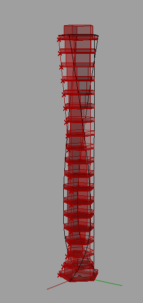
   Using these images from Google, I started my third procedural manipulation.  This procedure started by copying the surface vertically, 6 times to match the image.  Then I scaled down each surface following the bottom one by 10% increments, ending the top surface at 50% the size of the bottom surface.  Then I took the center tip control point of each surface and moved it vertically up by increments of 1".  This iteration stopped when the surfaces stopped; therefore it went from 1" at the bottom surface to a 6" move of the control point at the top surface.  Hence my Japanese house roof that looks more like a Christmas tree.


    I began to contemplate why the roofs were made like this.  I thought that at least one of the reasons might be to try and allow as much sunlight into the house as possible, and if it was not a reason, it was still an interesting concept to me anyway.  So my fourth procedural manipulation followed the idea of trying to maximize sunlight into a building.  I choose to only work with one side of the building's multiple roofs, in elevation view, in order to simplify my model.
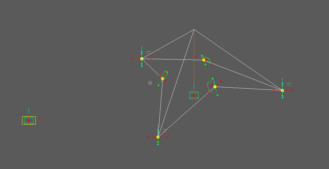
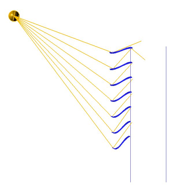
    I started this manipulation by going back to my original surface and mirroring half of the surface below the horizontal line at the base of the surface.  The result was an "S" shape.  I then modeled a sun and created rays of light to a vertical line of my surfaces representing the multiple roofs along the side of my building.  I then rotated each "S" about its building side end by multiples of 5 degrees.  I stopped at the top at 25 degrees from horizontal, thinking that at least some slope was still necessary for rain dispersion.  At the bottom of my line I stopped at 55 degrees, thinking too much slope would not allow for light penetration.  Then I moved the control points of the bottom end of each surface by 0.2" increments from top to bottom (but skipping the top surface), in order to create a "lip" that I felt could reflect the light toward the house.  I finished my procedural manipulation by repeating the "lip" process but in the opposite direction to the other edge.  This was thinking that the light would then reflect into the house.  As I looked at my final model, I didn't know if this is how light would actually behave, maybe it would be more realistic for the flow of water, but none-the-less the idea to study how to actually maximize light in a building would be an interesting one.


    I end this blog with a funny but enjoyable image I came across whilst doing the research for this project.  So, I felt like I should share the laugh, and more seriously, the creativity in an architectural design of a house with the rest of the class.